FRRouting. No clickbaits
No preface, no chit-chat. Let’s go.
Let’s build a network without any hardware switches or routers.
So, we’ve got two client hosts and one Linux box. The hosts are in the same subnet. We need to make them talk to each other. Basically, we gotta turn that Linux into a dumb D-link switch. Easy peasy:

Alright, this is a piece of cake. Install bridge-utils, whip up a bridge, toss those interfaces into the bridge, don’t forget to bring it up, and boom—voilà!
apt install bridge-utils
brctl addbr Bridge1
brctl addif Bridge1 ens4
brctl addif Bridge1 ens5
ip link set up ens4
ip link set up ens5asd
ip link set up dev Bridge1
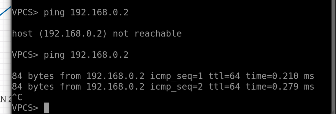
Pings are flying between the hosts. Hooray, we just built the dumbest switch in the world! Even MACs are visible:
root@ubuntu:~# brctl showmacs Bridge1
 port no	mac addr		is local?	ageing timer
 2	00:50:79:66:68:32	no		  84.50
 1	00:50:79:66:68:33	no		  84.50
 1	50:4d:8c:00:35:01	yes		   0.00
 1	50:4d:8c:00:35:01	yes		   0.00
 2	50:4d:8c:00:35:02	yes		   0.00
 2	50:4d:8c:00:35:02	yes		   0.00
So, the stuff marked as “is not local” — that’s our hosts. Now, let’s teach our switch to understand VLANs, and we’ll turn the second Linux box into a simple router.Traffic from the host will hit an “access” port, get tagged with an 802.1q tag, head into a “trunk,” and then get routed up the chain.
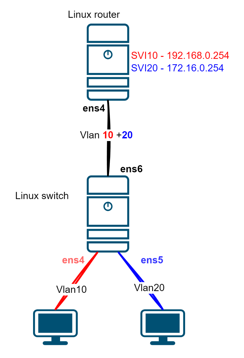
Now, on our Linux switch, we’re gonna need two bridges. One for each VLAN.
#Getting rid of the old bridge
ip link set down Bridge1
brctl delbr Bridge1

# Adding a couple of new ones
brctl addbr brVlan10
brctl addbr brVlan20
ip link set up brVlan10
ip link set up brVlan20
brctl addif brVlan10 ens4
brctl addif brVlan20 ens5

# Creating interfaces like "Vlan" on our uplink
ip link add link ens6 name Vlan10 type vlan id 10
ip link add link ens6 name Vlan20 type vlan id 20
ip link set up dev ens6

#Pushing them into bridges
brctl addif brVlan10 Vlan10
brctl addif brVlan20 Vlan20
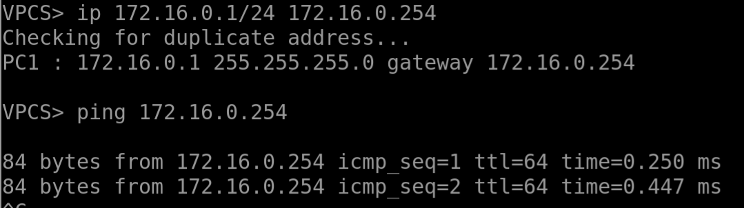
Alright, now if we try to ping the gateway from the first host and take a peek at ens6, we’ll see some totally normal ARP requests—but here’s the kicker: they’re tagged with a dot1.q tag, number 10
No responses — nobody’s there to reply. Let’s set up the Linux router sitting higher up in the chain.
# Here we will raise a couple of interfaces of the VLAN type and assign addresses
ip link add link ens4 name SVI10 type vlan id 10
ip link add link ens4 name SVI20 type vlan id 20
ip link set up ens4
ip addr add 192.168.0.254/24 dev SVI10
ip addr add 172.16.0.254/24 dev SVI20
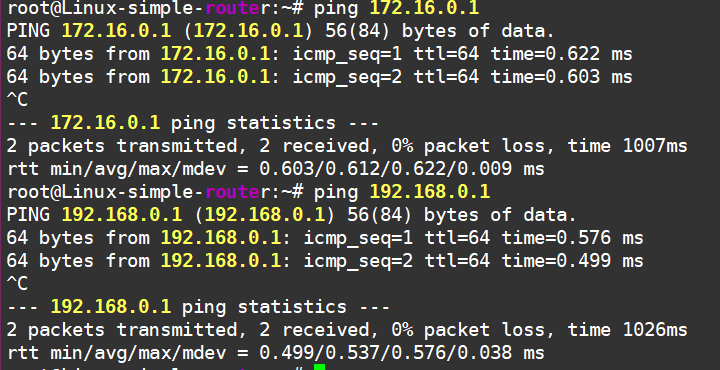
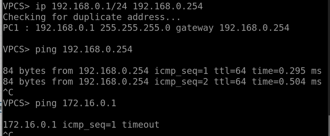
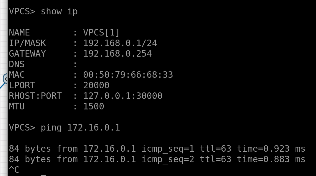
Now we can ping our hosts from here.
But wait, the hosts can’t ping each other, even though our brand-new gateway is reachable.
Oh right, we forgot to enable the routing function on the Linux router! Let’s fix that.
root@ubuntu:~# sysctl net.ipv4.ip_forward
net.ipv4.ip_forward = 0
root@ubuntu:~# sysctl -w net.ipv4.ip_forward=1
net.ipv4.ip_forward = 1
And there we go—pings are flying now.
So, in short, we’ve learned how to turn Linux into a switch and a router! Not bad, huh?
Alright, next let’s dive into the smallest Internet in the world with this setup:
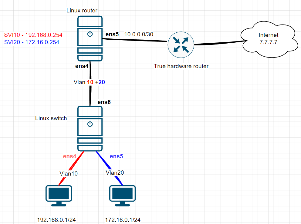
We’ll add a real hardware router to the scheme, set up a P2P link to the Linux router, and do the same thing on the Linux side:
# harware router settings:
True-Hardware-router-0#show run int et1
interface Ethernet1
   description Linux-router
   no switchport
   ip address 10.0.0.1/31

#  Linux router set up
ip addr add 10.0.0.0/31 dev ens5
ip link set up dev ens5
Pings are flying between the routers, but they’re not reaching the Internet from Linux :(
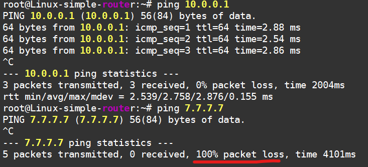
That’s because Linux has no clue how to get to this Internet of ours—it doesn’t even care. But we’ll help it out by adding a static route to the Internet through the hardware router:
ip r add 7.7.7.7/32 via 10.0.0.1 dev ens5
Now we’re chillin’.
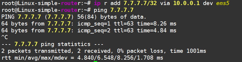
Linux can reach the "Internet" now!
But hey, we didn’t set up this Internet just for Linux-router. Nobody needs a network infrastructure in a vacuum—we’re here to provide services to the end hosts. So, what’s the situation now?
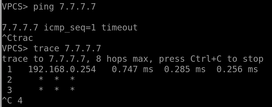
No luck—the traffic reaches the gateway and just kinda gets stuck there. But if you take a dump on the outgoing Internet interface, you’ll see the traffic heading towards the hardware router:
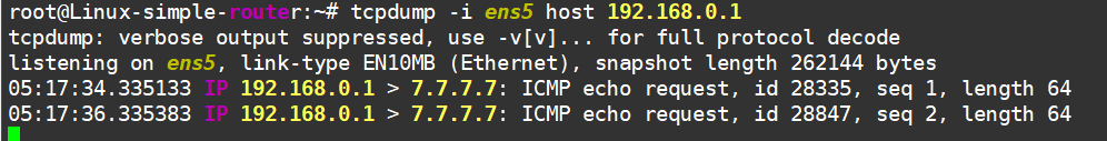
…and no replies are coming back :(
If we keep digging, we’ll see that the packet actually makes it to the Internet and even comes back! But that hardware router isn’t sending it back into our Linux-based local network. Ugh, it’s those cursed routes again—it just doesn’t know where our client networks live. We never set up the routing, after all.Alright, fine, let’s sprinkle in some static routes and call it a day.
Better now:
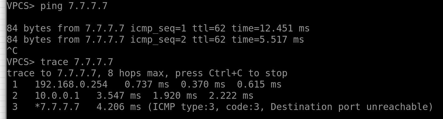
Oh, we have internet on our end-hosts!!
Alright, so we’ve got the routing sorted, but when the network grows, manually slapping together static routes gets boring and risky for network stability. What we really need is some IaC (Infrastructure as Code) magic—where a mindless machine spreads static routes across the network. But hey, the modern world isn’t quite ready for that yet, so we’re sticking with dynamic routing protocols for now.
The catch? These protocols need a control plane—some kind of daemon (or a bunch of them) that chats with neighboring routers, swaps useful info, and ideally, programs the data plane too. That’s where the real fun begins!
Meet FRR!
Practice beats theory every time, so let’s just install FRR with a quick command.
apt install frr
And to keep things clean, let’s nuke those static routes we set up manually:
# Linux router
root@Linux-simple-router:~# ip r del 7.7.7.7/32 via 10.0.0.1 dev ens5

# hardware router:
True-Hardware-router-0(config)#no ip route 172.16.0.0/24 10.0.0.0
True-Hardware-router-0(config)#no ip route 192.168.0.0/24 10.0.0.0
Now, let’s set up the most divine dynamic routing protocol of them all — RIP — between our two routers.
On Linux, head to /etc/frr/daemons, enable RIP, and restart FRR:
sudo sed -i 's/^ripd=no/ripd=yes/' /etc/frr/daemons
sudo systemctl restart frr
Next, hop into the FRR command line using vtysh, where you’ll find a cozy Cisco-like CLI waiting for you. That’s where we’ll set up RIP:
Linux-simple-router# show run ripd
Building configuration...
...
router rip
 network 172.16.0.0/24
 network 192.168.0.0/24
 network 10.0.0.0/31
exit
!
end
Do the same thing on the other side—mirror the setup:
True-Hardware-router-0#show run | sec router.rip
router rip
   network 7.7.7.0/24
   network 10.0.0.0/31
   no shutdown
Now take a look—routes are flowing in, visible in FRR’s routing table:
Linux-simple-router# show ip ro rip

R>* 7.7.7.0/24 [120/2] via 10.0.0.1, ens5, weight 1, 04:46:17
and even in the Linux kernel’s routing table:
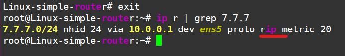
I won’t bother showing connectivity from the host to the “Internet”—just take my word for it. Besides, that’s not the point anymore. What is important is that we’ve used FRR to fill our host’s routing table with routes from external sources.
So, what’s this “FRR” thing anyway?
Let me drop a few facts. You can dig deeper on Google, any fancy LLM, or, you know, just check out their website: https://frrouting.org/.
It’s a suite of routing protocols for Linux (and apparently other Unix-like systems too).
A fork of the Quagga project (from 2017), which itself was a fork of Zebra (from 2003), which was born way back in the ‘90s…
Supports a bunch of protocols:
Simple and boring ones like RIP, OSPF, ISIS, BGP, LDP.
Complex and fun ones like NHRP, MP-BGP (including EVPN), Babel, and even signaling for services over SRv6.
Major contributors include NVIDIA, VMWare and Microsoft. Network OSes like Cumulus (https://www.nvidia.com/en-eu/networking/ethernet-switching/cumulus-linux/) and SONiC (https://sonicfoundation.dev/) run FRR under the hood.
And that’s pretty much all the theory you need on FRR. Next up, a quick detour into how this all works conceptually, and then we’ll dive into making our network even more complex.
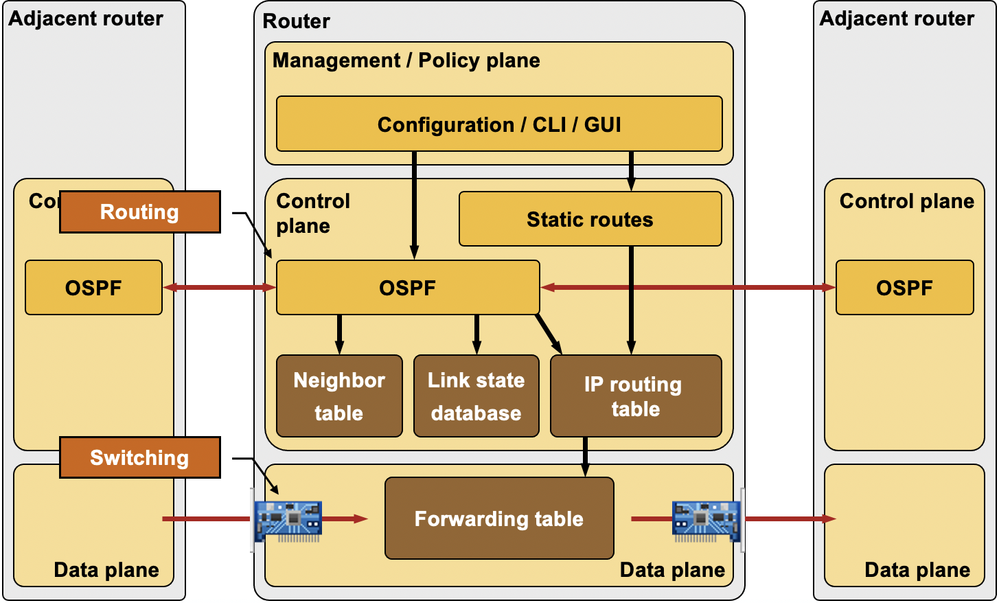
Quick reminder: any modern router has a few “planes”—we care about the Control Plane and the Data Plane. If we oversimplify it:
The Data Plane is all about shoving packets from one interface to another.
The Control Plane is the brains that tell the Data Plane how to do its job. Think of the Control Plane as the brain, and the Data Plane as the hands, feet, and heart.
Here’s a handy diagram from Ivan Pepelnjak
And one from me:
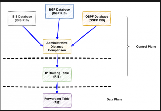
All these protocols do their thing and build their own little tables independently. Then, some kind of arbiter steps in, applies some criteria, and creates a single unified table — picking the “best” routes. This becomes the Routing Information Base (RIB). After that, it all gets programmed into the hardware chip, turning into the Forwarding Information Base (FIB).
But hey, this is just the basics—I’m just refreshing your memory here.
On the other hand, Linux has User Space and Kernel Space. Here’s a quick reminder (I don’t know the original source of this diagram—I’ve seen it floating around the internet without any attribution. If anyone knows the author or where it first appeared, let me know, and I’ll add the copyright).
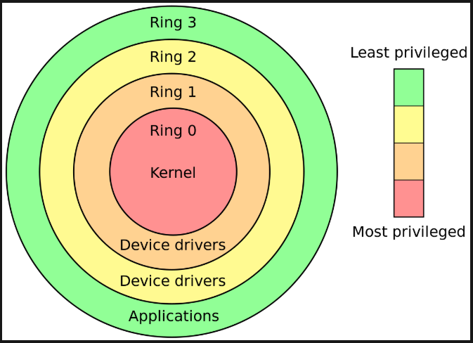
The author is unknown :( Sorry about that.
If we’re keeping it super simple—Kernel Space is where the operating system lives, and importantly for us, that’s where traffic forwarding happens (well, generally speaking, because there are cases where we move traffic processing to User Space—like with DPDK and all that jazz).
And User Space? That’s where applications run. For example, FRR and its daemons hang out there.
Now, piecing it all together, here’s what we’ve got:
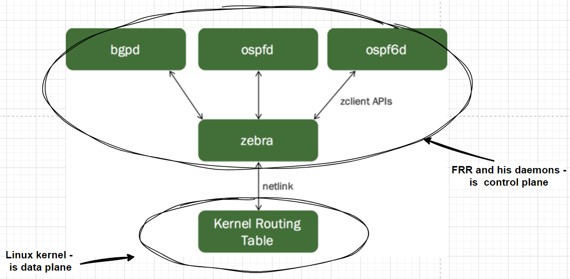
Based on https://docs.nvidia.com/networking-ethernet-software/cumulus-linux-510/Layer-3/FRRouting/
Control Plane lives in User Space. Data Plane lives in Kernel Space.
But there’s this murky part about how to shove routes from User Space into the kernel. If you look closely, there’s this mysterious thing called Netlink sitting between them. Netlink, roughly speaking, is an interface for communication between User Space and Kernel Space. It has its own “protocol,” or communication standard—which, obviously, makes sense because it’d be weird if it didn’t.
Probably the best resource on how Netlink works is, of course, kernel.org. And if you want to dive into the library for working with Netlink, check this out: https://www.infradead.org/~tgr/libnl/doc/core.html. But fair warning — it’s heavy on the math and technical jargon, and honestly, I don’t understand a thing there :(
For network folks, there’s packet capture, which you can check out in Wireshark. For now, let’s stop announcing the route from the “Internet,” enable a kernel module to snoop on Netlink, and take a peek at what’s going on:
# disable Uplink to the Internet
True-Hardware-router-0(config)#interface Ethernet2
True-Hardware-router-0(config-if-Et2)#shutdown
###
root@Linux-simple-router:~# modprobe nlmon
root@Linux-simple-router:~# ip link add nlmon0 type nlmon
root@Linux-simple-router:~# ip link set nlmon0 up
After this, a new interface called nlmon0 pops up in our system. Once we turn the network announcement back on, we can use good old tcpdump to see what’s happening on it:
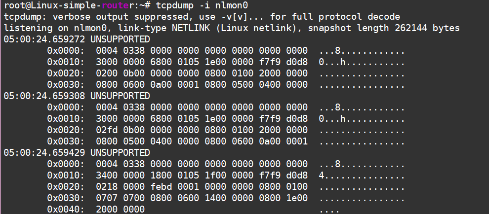
Turning on the network announcement from the neighboring router
Of course, it’s all gibberish at first glance—we need Wireshark magic:
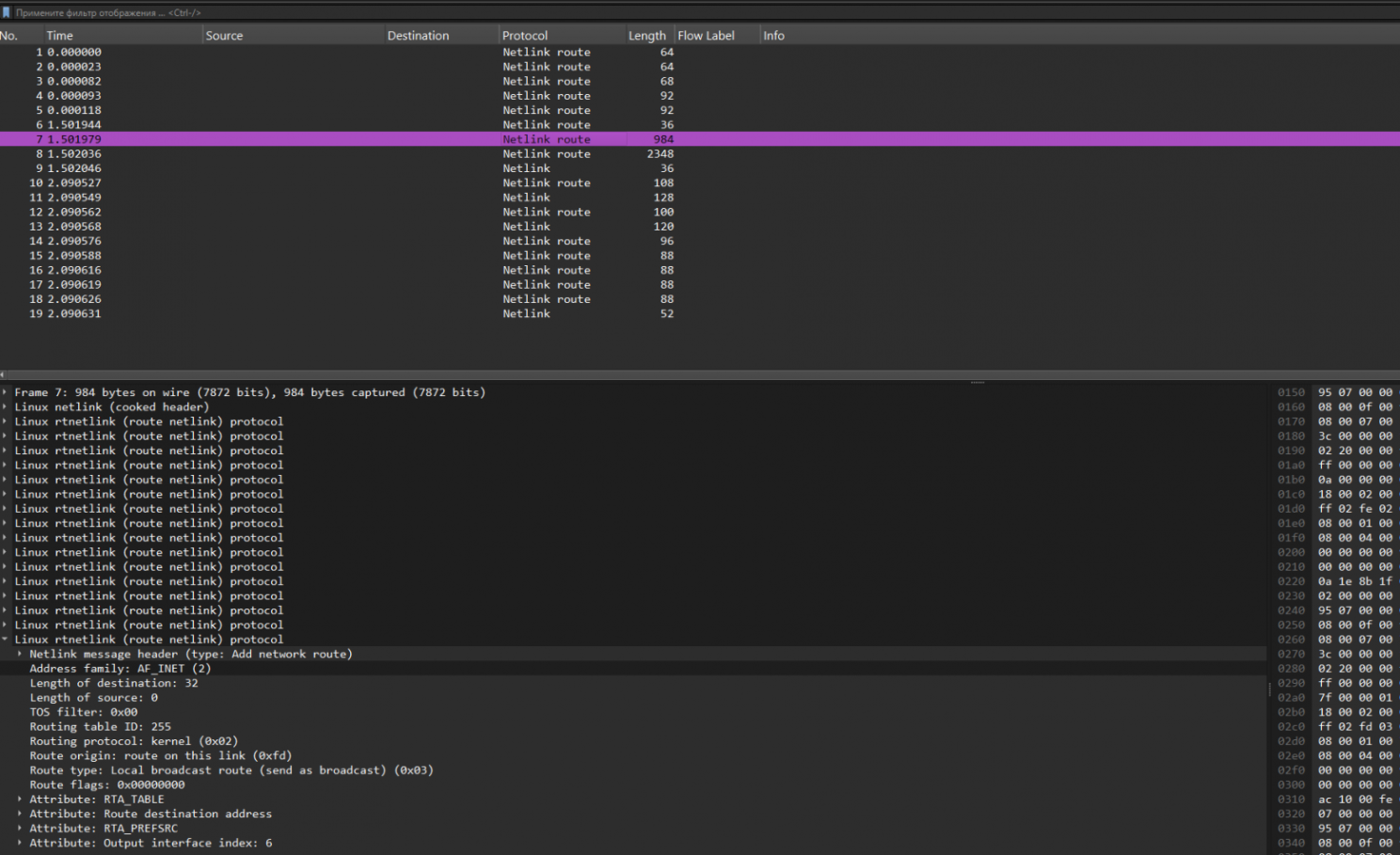
There’s a lot going on here too. We need to filter by “netlink-route.rt_family == 2”—that is, we’re looking for IPv4 route announcements. But even then, there’s still a ton of stuff….
So, we’re searching for anything related to the 7.7.7.0 network. Let’s convert that to a hexadecimal number and try searching in the “Data” field of the Netlink message attribute: “netlink.attr_data == 07.07.07.00”:
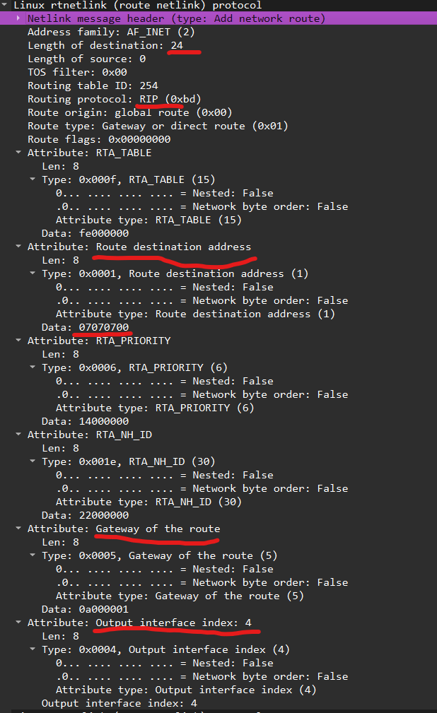
Here it is, flowing straight from User Space into Kernel Space. 🚀
I’ve highlighted what might be important in the screenshot:
- There’s a route to the network.
- There’s a route mask.
- There’s a next hop.
- There’s an outgoing interface.
What else do you need for a happy little route?
Okay, we’ve kinda sorted out the theory. That should be enough to keep us going for a couple of years. Now, let’s move on to something more fun!
Overlays with FRR. MPLS.
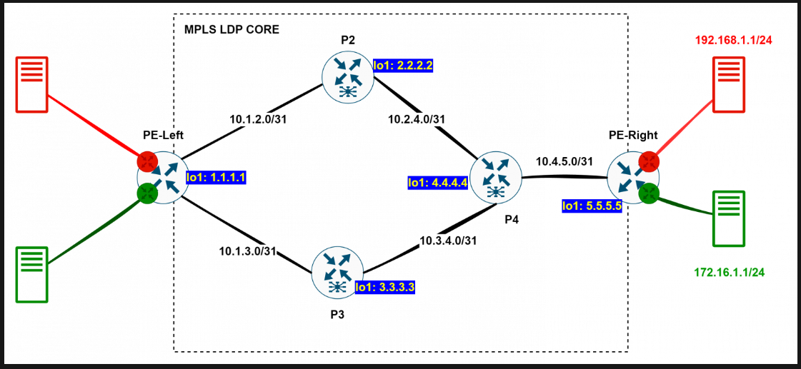
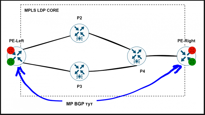
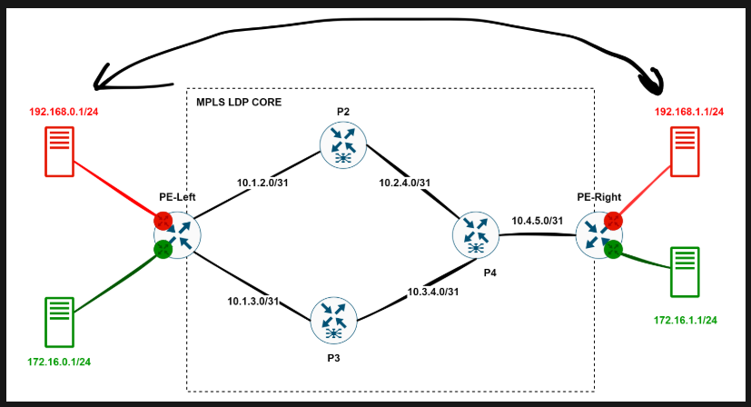
As everyone knows, MPLS can’t be a goal in itself. MPLS exists for services. Let’s set up the most typical use case—L3 VPN—with this topology:
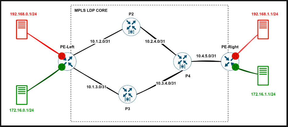
Everything that’s round is just regular Ubuntu boxes.
We’ve got a couple of VRF-aware routers where clients connect (Provider Edge - PE), and a network core that knows nothing about these VRFs—it just provides transport from PE to PE. As for the user traffic, we’ll wrap it in MPLS labels and tunnel it through.
First things first, we need to tell our Linux boxes to become MPLS-aware routers:
# lets enable kernel options
modprobe mpls_router
modprobe mpls_iptunnel
modprobe mpls_gso

# Let’s enable MPLS label processing on the interfaces.
sysctl -w net.mpls.conf.ens4.input=1
sysctl -w net.mpls.conf.ens5.input=1
sysctl -w net.mpls.conf.ens6.input=1

# How many labels can we use? A million should be enough for today.
sysctl -w net.mpls.platform_labels=1048575
We already know how to set up IP links between routers—just don’t forget to run sysctl -w net.ipv4.ip_forward=1 everywhere.
Now, all that’s left is to create red and green VRFs on our PE routers:
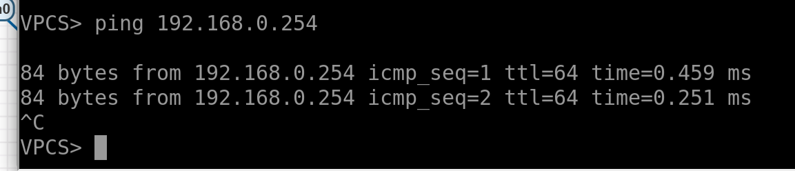
- Configure the red host on the left simply — give it an IP and a gateway. Do the same for the others:
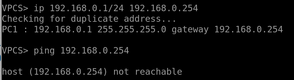
The gateway isn’t reachable yet.
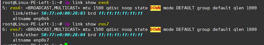
The interfaces on the left PE aren’t configured yet:
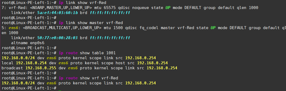
- Let’s place them in VRFs and assign addresses!
# Create a VRF and bind it to a dedicated routing table.
sudo ip link add vrf-Red type vrf table 1001
sudo ip link set dev vrf-Red up

# Shove our interface into this VRF, enable it, and assign an address.
sudo ip link set dev ens6  master vrf-Red
sudo ip addr add 192.168.0.254/24 dev ens6
sudo ip link set dev ens6 up
Now you can check the VRF’s status, see which interfaces are bound to it, and inspect its routing table.
- Do the same for the green VRF, remembering to bind it to a different routing table for traffic isolation:
sudo ip link add vrf-Green type vrf table 1002
sudo ip link set dev vrf-Green up
sudo ip link set dev ens7  master vrf-Green
sudo ip addr add 172.16.0.254/24 dev ens7
sudo ip link set dev ens7 up
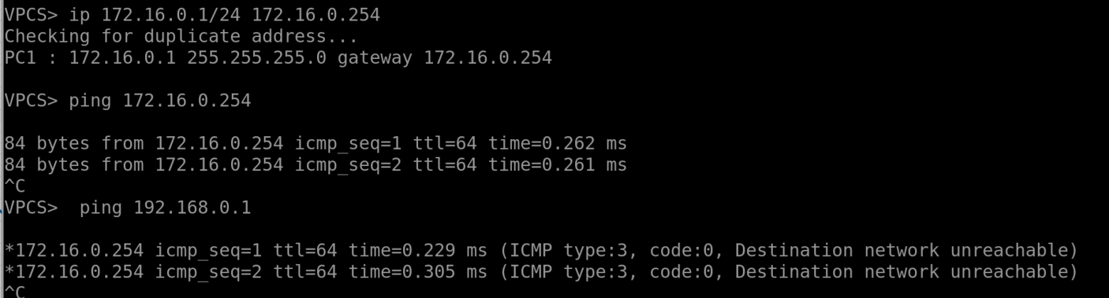
Now, the hosts can ping their gateways but can’t ping each other since they’re in different VRFs:
On the right PE, we’ll do the same but add a bit of entropy by using different routing tables and VRF names to show that this is all locally significant:
# First vrf:
sudo ip link add vrf-R type vrf table 108
sudo ip link set dev vrf-R up
sudo ip link set dev ens5  master vrf-R
sudo ip addr add 192.168.1.254/24 dev ens5
sudo ip link set dev ens5 up

# and the second one:
sudo ip link add vrf-G type vrf table 109
sudo ip link set dev vrf-G up
sudo ip link set dev ens6  master vrf-G
sudo ip addr add 172.16.1.254/24 dev ens6
sudo ip link set dev ens6 up
And, of course, you can test host reachability by pinging them directly from the VRFs
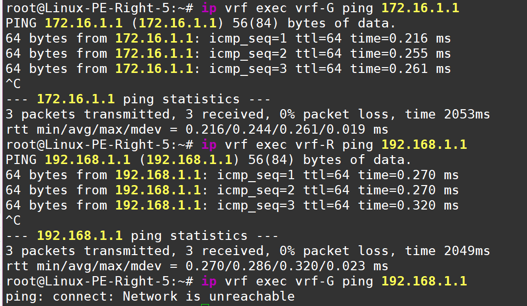
As we can see from Green vrf there no connectivity to Red one - serves them right!
What else do we need to do before diving into the MPLS setup with FRR? Add a new Loopback interface on all Linux routers—we’ll use this for all the control plane protocols (don’t forget to enable MPLS on the interface):
 ip link add name lo1 type dummy
 ip link set dev lo1 up
 sysctl -w net.mpls.conf.lo1.input=1
Okay, it seems like we’ve done everything we needed inside Linux. Now, we’ll work exclusively with FRR. Let’s revisit the diagram one more time:
Here’s the plan:
Set up a single OSPF domain to exchange Loopback addresses.
Configure MPLS LDP to exchange transport labels.
Once the left PE can reach the right PE using MPLS, we’ll add a bit of MP-BGP magic to exchange service labels and VRF routes.
???
PROFIT!
I’ll demonstrate the setup for the first two steps using the PE-Left <–> P2 connection—all other connections are configured similarly.
# Let’s hop into the FRR console.
root@Linux-PE-Left-1:~# vtysh

Hello, this is FRRouting (version 8.1).
Copyright 1996-2005 Kunihiro Ishiguro, et al.

# All configuration actions are done in configuration mode.
Linux-PE-Left-1# conf t

# Set up addresses on the Loopbacks.
Linux-PE-Left-1(config) int lo1
Linux-PE-Left-1(config-if) ip address 1.1.1.1/32
At this point, on the left PE, check the routing table to make sure we don’t see routes to P2—only connected networks:
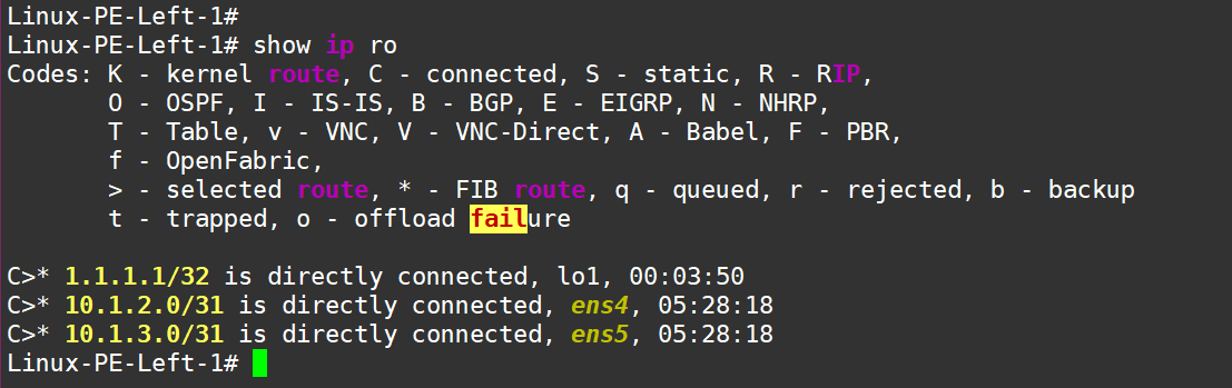
Next, configure OSPF, enable it on the new Loopback and on the interfaces facing other routers:
#### Left PE:
Linux-PE-Left-1 conf t
Linux-PE-Left-1(config) router ospf
Linux-PE-Left-1(config-router) network 1.1.1.1/32 area 0
Linux-PE-Left-1(config-router) network 10.1.2.0/31 area 0
Linux-PE-Left-1(config-router) network 10.1.3.0/31 area 0

#### P2:
Linux-P-2(config)# router ospf
ospfd is not running
Linux-P-2(config-router)#
Hmm… something seems off on P2 — ospfd isn’t running there (weird that the left PE didn’t have this issue—probably because I set up the daemon there earlier. Oh well, my bad). Anyway, let’s fix it—enable ospfd, ldpd, and bgpd (even though BGP isn’t needed everywhere) by editing the /etc/frr/daemons file.
sudo sed -i 's/^ospfd=no/ospfd=yes/' /etc/frr/daemons
sudo sed -i 's/^ldpd=no/ldpd=yes/' /etc/frr/daemons
sudo sed -i 's/^bgpd=no/bgpd=yes/' /etc/frr/daemons
# restart FRR
sudo systemctl restart frr
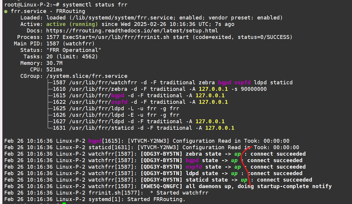
Now, check the status to make sure all the necessary daemons are running—“Green - OK.”
Let’s finish configuring OSPF on P2. Here’s the config:
router ospf
 network 2.2.2.2/32 area 0
 network 10.1.2.0/31 area 0
 network 10.2.4.0/31 area 0
exit
# Do not forget to  "wr", beacause config will be losed after FRR restart:
Linux-P-2# wr
Note: this version of vtysh never writes vtysh.conf
Building Configuration...
Integrated configuration saved to /etc/frr/frr.conf
[OK]
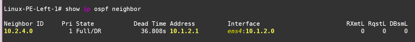
If you check the traffic dump between PE-Left and P2 at this point, you’ll see some nice OSPF messages—sessions are up, LSAs are flying around:
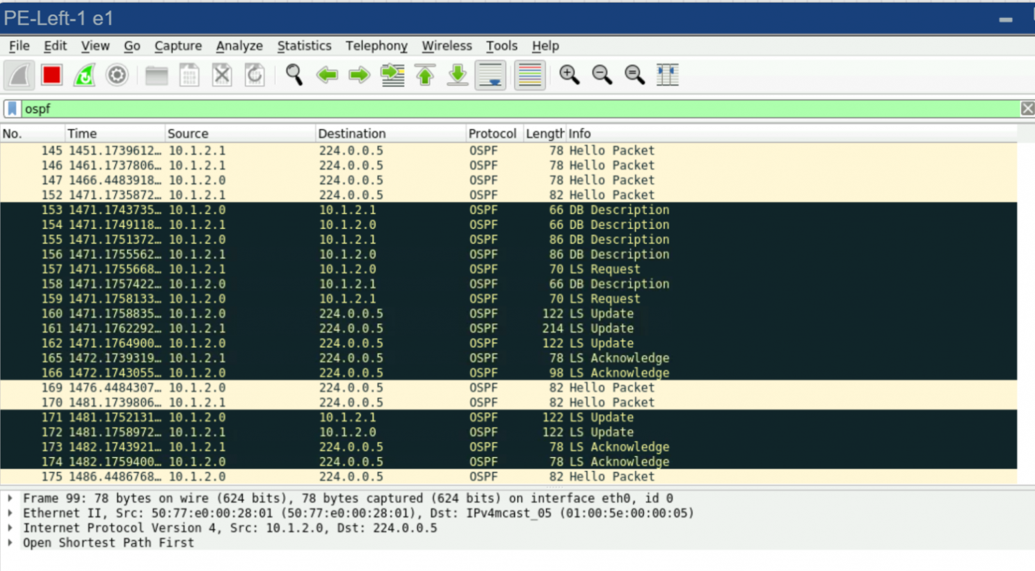

PE-Left
And P-2
Roll out this setup (OSPF config) to all the other routers, and then we’ll move on to configuring LDP.
# Let’s configure LDP as simply as possible
# Set the router-id, Enable it on the necessary interfaces
# Specify which address to use for TCP connections
mpls ldp
 router-id 1.1.1.1
 address-family ipv4
  discovery transport-address 1.1.1.1
  interface ens4
  interface ens5
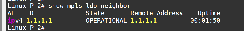
Do the same on P2, and check the traffic dump:
LDP is running now
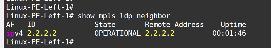
Neighbors are up:
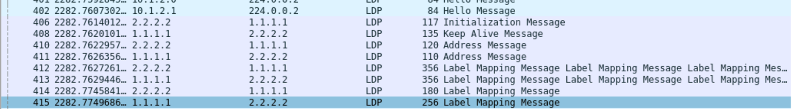
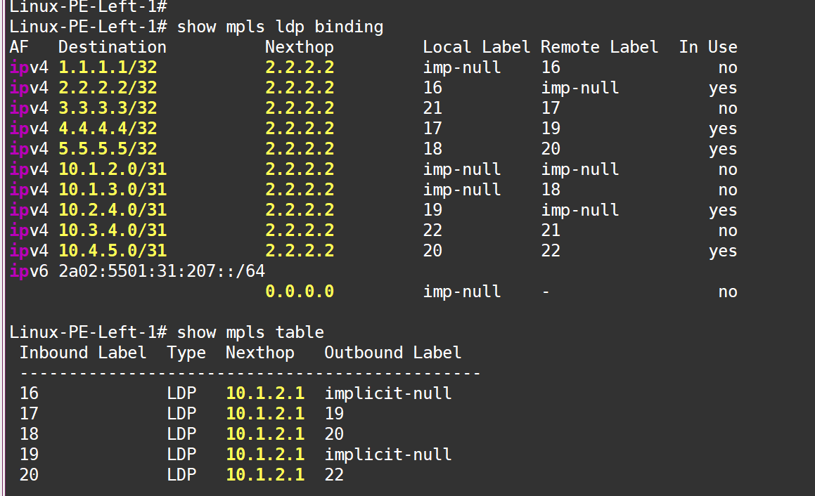
Labels are configured:
Now, roll out this LDP setup to all routers. If we ping from the Loopback of the left PE (1.1.1.1) to the Loopback of the right PE (5.5.5.5) and check the traffic dump between P2 and P4, we’ll see the traffic wrapped in an MPLS label:
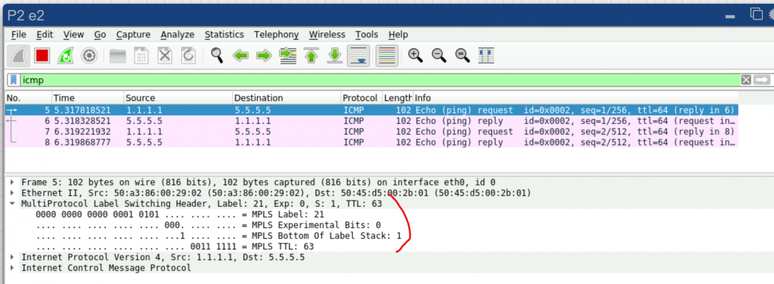
Good! It seems like everything’s working. But again—MPLS by itself doesn’t give us any real benefit. We need services!
For services, we need BGP in the VPNv4 address family. BGP will be established between the left and right PE routers:
# ==  PE Left: ==
router bgp 65001
 bgp router-id 1.1.1.1
 neighbor 5.5.5.5 remote-as 65001
 !
 address-family vpnv4 unicast
  neighbor 5.5.5.5 activate
  neighbor 5.5.5.5 send-community extended
  exit-address-family

#############################
# ==  PE Right: ==
router bgp 65001
 bgp router-id 5.5.5.5
 neighbor 1.1.1.1 remote-as 65001
 neighbor 1.1.1.1 update-source 5.5.5.5
 !
 address-family ipv4 vpn
  neighbor 1.1.1.1 activate
 exit-address-family
exit
BGP is up on both PEs, but so far, no one is announcing anything to anyone:
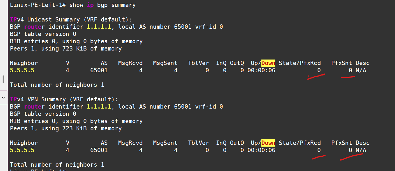
In the IPv4 AF, we don’t even plan to announce anything. We can even kill the session:
# ==  PE Left: ==
router bgp 65001
 address-family ipv4 unicast
  no neighbor 5.5.5.5 activate
 exit-address-family

# ==  PE Right: ==
router bgp 65001
 address-family ipv4 unicast
  no neighbor 1.1.1.1 activate
 exit-address-family
Now, all that’s left is to add route announcements from the VRFs.
At the moment, the routing tables in the VRFs look like this — only local connected routes are visible:
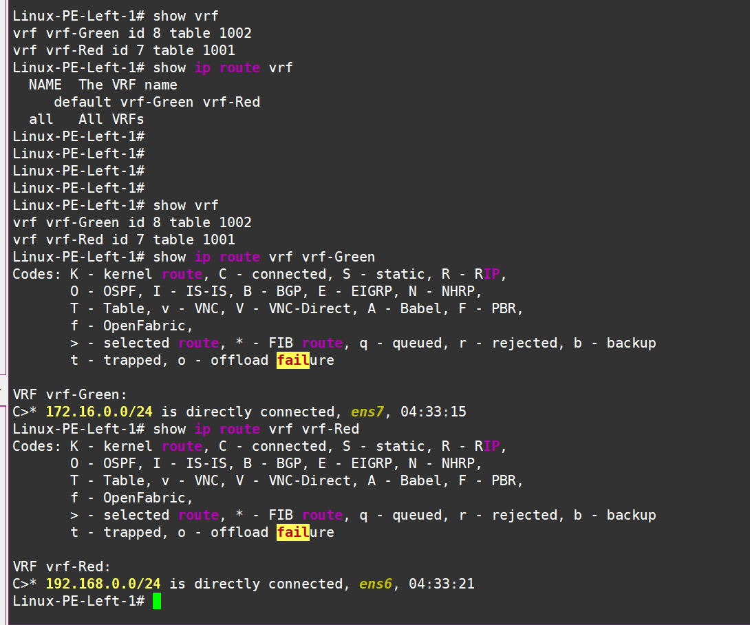
PE Left
PE Right
Let’s fine-tune our BGP process like this:
#####
#Configuring the left PE
#####
# For the green VRF
router bgp 65001 vrf vrf-Green
address-family ipv4 unicast
  redistribute connected
  label vpn export auto
  rd vpn export 1.1.1.1:2
  rt vpn both 65001:2
  export vpn
  import vpn
 exit-address-family
exit

# and for the red one:
router bgp 65001 vrf vrf-Red
 address-family ipv4 unicast
  redistribute connected
  label vpn export auto
  rd vpn export 1.1.1.1:3
  rt vpn both 65001:3
  export vpn
  import vpn
 exit-address-family
exit
Don’t forget to keep an eye on all the RD/RT stuff.
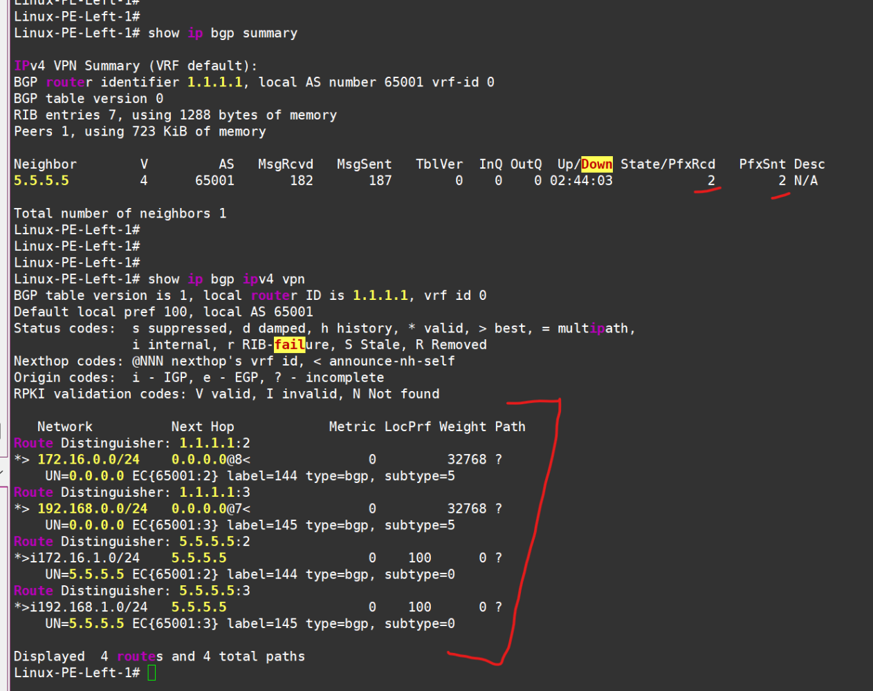
After mirroring the setup on the other side (it’s better to keep RT the same for each VRF, but make RD unique for each router+VRF combo), we should see that some routes are being sent and received in the VPNv4 AF — and not just any routes, but ones marked with communities and labels:
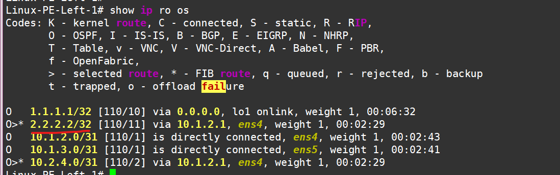
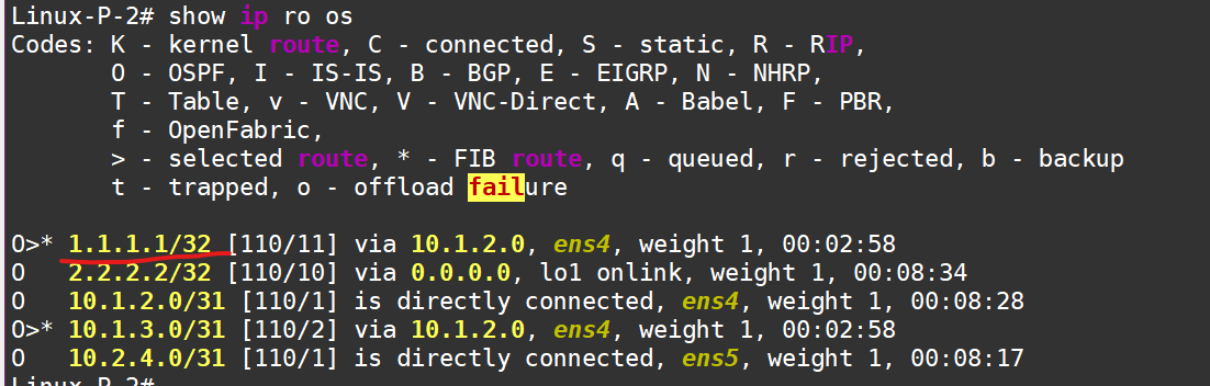
The routes have successfully made their way into the routing tables of the respective VRFs:
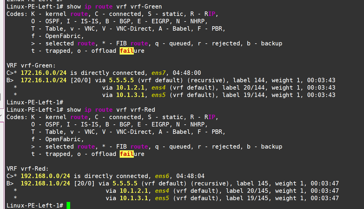
Left PE see routes in vrf!
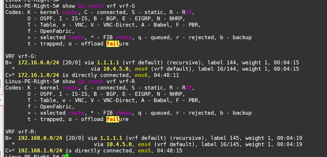
And right PE see rotues in vrf!
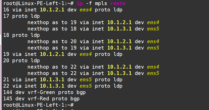
From the kernel’s perspective, we can see the routes in the VRF, and it even tells us which labels to add where:
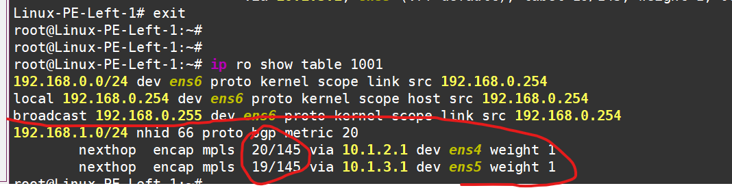
These labels can be decoded as follows:
Now, let’s test the connectivity in the red VRF, for example:
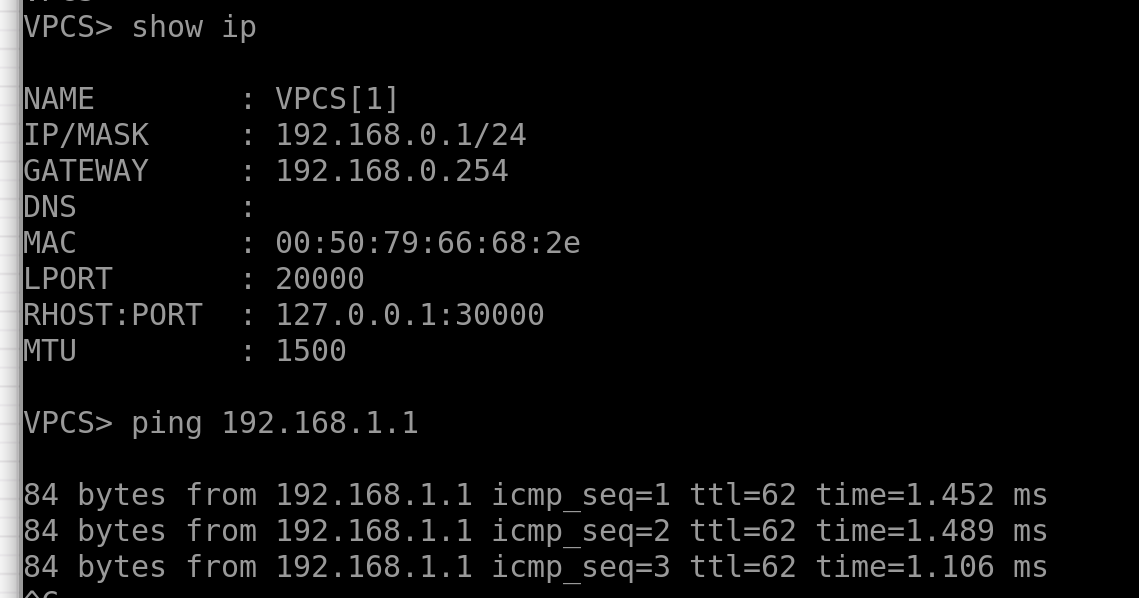
And if we set up Wireshark somewhere between P2 and P4, we’ll see something beautiful:
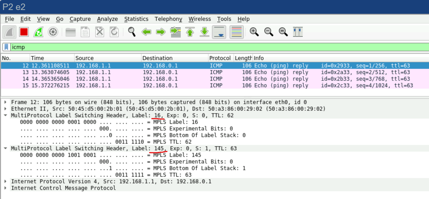
As expected, one label for the service (VRF) and another label for transport.
Alright, that’s enough MPLS for us. 🚀
Overlays with FRR. EVPN/VXLAN and a Touch of Magic.
Now, let’s dive into the trendiest thing—EVPN/VXLAN—with the goal of creating an L2VPN. We need to build this topology
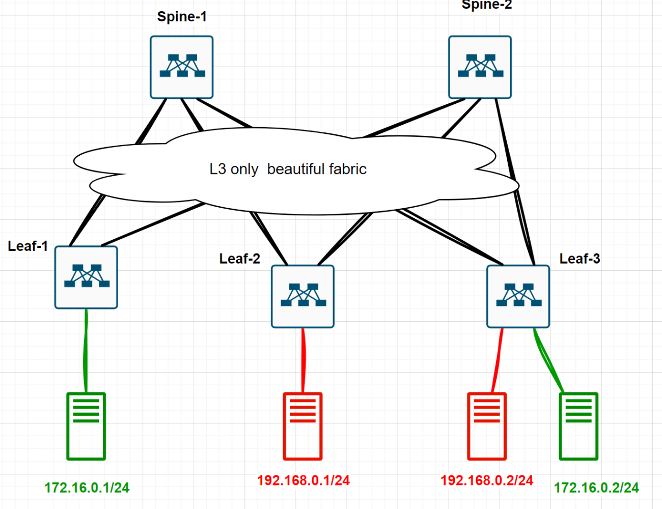
There are three conditions:
All network devices are Linux hosts running FRR.
Between network devices, there’s only IP routing—no VLAN stretching here.
We need to provide L2 connectivity between the green hosts, making them think they’re in the same broadcast domain.
But honestly, I’m way too lazy to do all this manually. Way too lazy. So, I’ll resort to the good old YAML. Yep, I’m going to build this entire lab with one tiny YAML file.
I’ll do this using the netlab tools project—check it out here: https://netlab.tools/. Ivan Pepelnjak , thanks again )
I’ve already written a detailed guide on how to install, use, and why netlab tools are awesome in this cool article of mine ( ⚠️ Warning, it’s lead to Linkedin!) So, it’s better to read that first to understand what’s coming next — otherwise, it might genuinely seem like magic.
Alright, I log into the host where I’ve already installed netlab tools + containerlab (https://containerlab.dev/ — this is the “provider” for containerized network devices in netlab). I create an empty folder and a new empty file called topology.yml:
roman@netlab-test:~$
roman@netlab-test:~$ mkdir Magic_EVPN_LAB
roman@netlab-test:~$ cd Magic_EVPN_LAB/
roman@netlab-test:~/Magic_EVPN_LAB$ touch topology.yml
roman@netlab-test:~/Magic_EVPN_LAB$ cat topology.yml
The file is empty, and I’ll paste the following YAML into it with some comments along the way:
---
# Specify containerlab as the virtualization provider
provider: clab

# By default, all devices will be FRR instances
defaults.device: frr

#   Enable the "fabric" plugin—this will automatically build us a Leaf-Spine topology
plugin: [ fabric ]

# We need two spines and three leaves
fabric.spines: 2
fabric.leafs: 3

# Default ASN for BGP
bgp.as: 65000


# Describe common parameters for groups
groups:
  # If there are no objects in the group, create them automatically
  _auto_create: True
    # Modules to be used on the leaves
    # We need OSPF for the underlay, BGP for the overlay
    # EVPN, of course, VXLAN, and VLANs to place hosts in different VLANs
  leafs:
    module: [ospf,bgp,evpn,vxlan,vlan]
    # Modules to be used on the spines
    # Also, specify that spines will act as route reflectors for BGPbgp
  spines:
    module: [ospf,bgp,evpn]
    bgp.rr: True

# Create four Linux hosts
  hosts:
    members: [GreenHost1, GreenHost2, RedHost1, RedHost2]
    device: linux

# The simplest VLAN configuration mode—just bridge everything in the same VLAN
# No routing involved
vlan.mode: bridge


# Here, we first "plug" the hosts into the leaves
# Second, we assign VLANs to the created links—Green and Red, as shown in the diagram
vlans:
  Green:
    links: [GreenHost1-L1,GreenHost2-L3]
  Red:
    links: [RedHost1-L2, RedHost2-L3]
That’s actually it!
Now, let’s just run this with a simple little command: “sudo netlab up”, and watch the magic happen. Here are a couple of screenshots of what’s going on
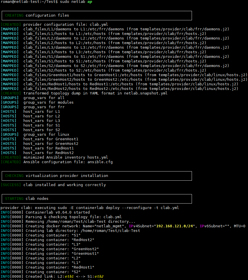
Something’s happening...
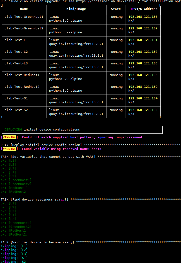
Oh, what’s going on...
The machinery kicks in, creating and launching all the necessary containers (FRR as network devices + regular Alpine as hosts), assembling everything into the desired topology, creating all the required bridges on the host, and running Ansible on the hosts to deploy all the necessary configs.
Let’s see what we’ve got:
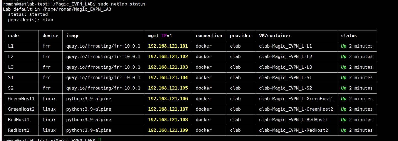
Leaves and spines with FRR. Hosts with Linux.You can also see what this looks like graphically. Let’s create a graphical topology:
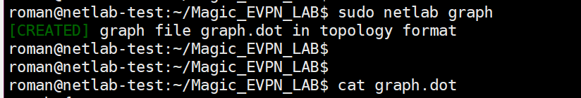
graph {
  bgcolor="transparent"
  node [shape=box, style="rounded,filled" fontname=Verdana]
  edge [fontname=Verdana labelfontsize=10 labeldistance=1.5]
  subgraph cluster_AS_65000 {
    bgcolor="#e8e8e8"
    fontname=Verdana
    margin=16
    label="AS 65000"
    "L1" [
      label="L1 [frr]\n10.0.0.1/32"
      fillcolor="#ff9f01"
      margin="0.3,0.1"
    ]
    "L2" [
      label="L2 [frr]\n10.0.0.2/32"
      fillcolor="#ff9f01"
      margin="0.3,0.1"
    ]
    "L3" [
      label="L3 [frr]\n10.0.0.3/32"
      fillcolor="#ff9f01"
      margin="0.3,0.1"
    ]
    "S1" [
      label="S1 [frr]\n10.0.0.4/32"
      fillcolor="#ff9f01"
      margin="0.3,0.1"
    ]
    "S2" [
      label="S2 [frr]\n10.0.0.5/32"
      fillcolor="#ff9f01"
      margin="0.3,0.1"
    ]
  }
 "L1" -- "S1" [ ]
 "L1" -- "S2" [ ]
 "L2" -- "S1" [ ]
 "L2" -- "S2" [ ]
 "L3" -- "S1" [ ]
 "L3" -- "S2" [ ]
  "Magic_EVPN_7" [style=filled fillcolor="#d1bfab" fontsize=11 margin="0.3,0.1" label="172.16.0.0/24"]
 "GreenHost1" -- "Magic_EVPN_7" [  ]
 "L1" -- "Magic_EVPN_7" [  ]
  "Magic_EVPN_8" [style=filled fillcolor="#d1bfab" fontsize=11 margin="0.3,0.1" label="172.16.0.0/24"]
 "GreenHost2" -- "Magic_EVPN_8" [  ]
 "L3" -- "Magic_EVPN_8" [  ]
  "Magic_EVPN_9" [style=filled fillcolor="#d1bfab" fontsize=11 margin="0.3,0.1" label="172.16.1.0/24"]
 "RedHost1" -- "Magic_EVPN_9" [  ]
 "L2" -- "Magic_EVPN_9" [  ]
  "Magic_EVPN_10" [style=filled fillcolor="#d1bfab" fontsize=11 margin="0.3,0.1" label="172.16.1.0/24"]
 "RedHost2" -- "Magic_EVPN_10" [  ]
 "L3" -- "Magic_EVPN_10" [  ]
}
Parsing this in your head is tough, so let’s head over to https://dreampuf.github.io/GraphvizOnline and turn these letters and numbers into a picture:
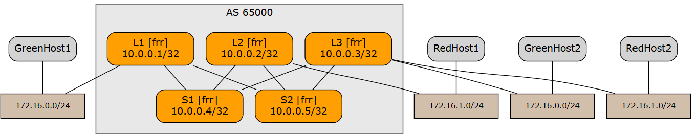
our topology
Now, let’s try to drop into the shell of Green Host 1 and ping Green Host 2:
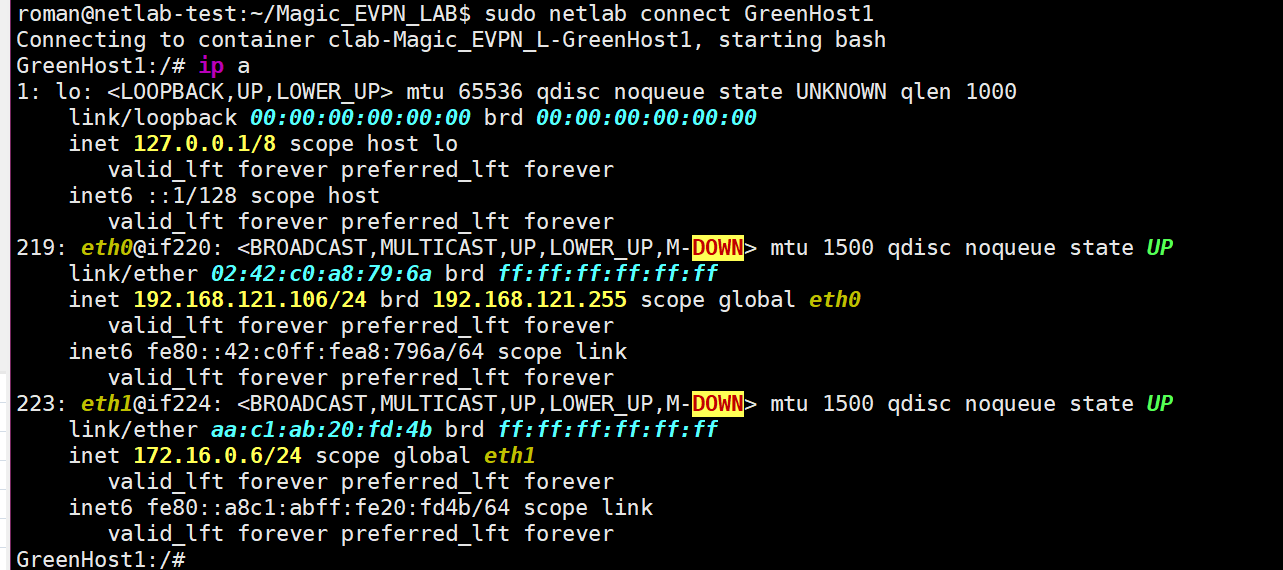
Got into the shell, but what to ping? Not sure. But now we know the IP of our GreenHost1: 172.16.0.6 and its MAC address: aa:c1:ab:20:fd:4b.Let’s check from the other side:
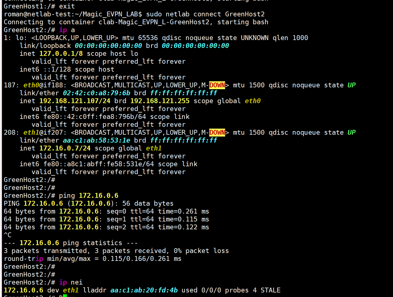
Voilà, pings are working, and the neighbor is visible, like it’s brother. And what about Leaf 1, for example?
Go into the shell, land in Linux, and enter the FRR console the usual way. Let’s see what netlab has configured for us this time (I’ll paste the listing as text, just this once):
GreenHost2:/# exit
roman@netlab-test:~/Magic_EVPN_LAB$ sudo netlab connect L1
Connecting to container clab-Magic_EVPN_L-L1, starting bash

Use vtysh to connect to FRR daemon

L1(bash)#
L1(bash)# vtysh

Hello, this is FRRouting (version 10.0.1_git).
Copyright 1996-2005 Kunihiro Ishiguro, et al.

2025/02/26 16:30:19 [YDG3W-JND95] FD Limit set: 1048576 is stupidly large.  Is this what you intended?  Consider using --limit-fds also limiting size to 100000
L1#
L1#
L1#
L1# show run
Building configuration...

Current configuration:
!
frr version 10.0.1_git
frr defaults datacenter
hostname L1
no ipv6 forwarding
service integrated-vtysh-config
!
vrf mgmt
exit-vrf
!
interface eth1
 description L1 -> S1
 ip address 10.1.0.1/30
 ip ospf area 0.0.0.0
 ip ospf network point-to-point
exit
!
interface eth2
 description L1 -> S2
 ip address 10.1.0.5/30
 ip ospf area 0.0.0.0
 ip ospf network point-to-point
exit
!
interface eth3
 description [Access VLAN Green] L1 -> GreenHost1
exit
!
interface lo
 ip address 10.0.0.1/32
 ip ospf area 0.0.0.0
exit
!
interface vlan1000
 description VLAN Green (1000) -> [GreenHost1,GreenHost2,L3]
exit
!
router bgp 65000
 bgp router-id 10.0.0.1
 no bgp default ipv4-unicast
 bgp bestpath as-path multipath-relax
 neighbor 10.0.0.4 remote-as 65000
 neighbor 10.0.0.4 description S1
 neighbor 10.0.0.4 update-source lo
 neighbor 10.0.0.5 remote-as 65000
 neighbor 10.0.0.5 description S2
 neighbor 10.0.0.5 update-source lo
 !
 address-family ipv4 unicast
  network 10.0.0.1/32
  neighbor 10.0.0.4 activate
  neighbor 10.0.0.4 next-hop-self
  neighbor 10.0.0.5 activate
  neighbor 10.0.0.5 next-hop-self
 exit-address-family
 !
 address-family l2vpn evpn
  neighbor 10.0.0.4 activate
  neighbor 10.0.0.4 soft-reconfiguration inbound
  neighbor 10.0.0.5 activate
  neighbor 10.0.0.5 soft-reconfiguration inbound
  advertise-all-vni
  vni 101000
   rd 10.0.0.1:1000
   route-target import 65000:1000
   route-target export 65000:1000
  exit-vni
  advertise-svi-ip
  advertise ipv4 unicast
 exit-address-family
exit
!
router ospf
 ospf router-id 10.0.0.1
 timers throttle spf 10 50 500
 timers throttle lsa all 100
 timers lsa min-arrival 100
exit
!
end
The container we dropped into is a Linux box running FRR. It has regular L3 links set up to the spines, and OSPF is configured to reach them:
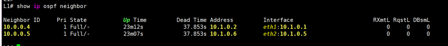
ospf
OSPF is needed to exchange Loopback addresses—so all leaves can see each other and the spines. Then, BGP EVPN sessions are built to these spines:
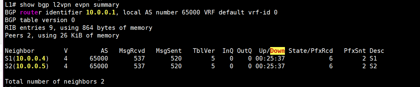
bgp evpn
Every leaf does THIS with every spine, sending its local EVPN routes and receiving routes from other leaves in return. This is how L2 connectivity between the hosts is ultimately achieved:
For a deeper dive into how, why, and EVPN/VXLAN works, please follow Toni Pasanen and his materials :)
Just in case, here’s the FRR config from a spine, so that EVERYTHING FINALLY MAKES SENSE:
L1(bash)# exit
logout
roman@netlab-test:~/Magic_EVPN_LAB$ sudo netlab connect S1
Connecting to container clab-Magic_EVPN_L-S1, starting bash

Use vtysh to connect to FRR daemon

S1(bash)# vtysh

Hello, this is FRRouting (version 10.0.1_git).
Copyright 1996-2005 Kunihiro Ishiguro, et al.

2025/02/26 16:43:11 [YDG3W-JND95] FD Limit set: 1048576 is stupidly large.  Is this what you intended?  Consider using --limit-fds also limiting size to 100000
S1# show run
Building configuration...

Current configuration:
!
frr version 10.0.1_git
frr defaults datacenter
hostname S1
no ipv6 forwarding
service integrated-vtysh-config
!
vrf mgmt
exit-vrf
!
interface eth1
 description S1 -> L1
 ip address 10.1.0.2/30
 ip ospf area 0.0.0.0
 ip ospf network point-to-point
exit
!
interface eth2
 description S1 -> L2
 ip address 10.1.0.10/30
 ip ospf area 0.0.0.0
 ip ospf network point-to-point
exit
!
interface eth3
 description S1 -> L3
 ip address 10.1.0.18/30
 ip ospf area 0.0.0.0
 ip ospf network point-to-point
exit
!
interface lo
 ip address 10.0.0.4/32
 ip ospf area 0.0.0.0
exit
!
router bgp 65000
 bgp router-id 10.0.0.4
 no bgp default ipv4-unicast
 bgp cluster-id 10.0.0.4
 bgp bestpath as-path multipath-relax
 neighbor 10.0.0.1 remote-as 65000
 neighbor 10.0.0.1 description L1
 neighbor 10.0.0.1 update-source lo
 neighbor 10.0.0.2 remote-as 65000
 neighbor 10.0.0.2 description L2
 neighbor 10.0.0.2 update-source lo
 neighbor 10.0.0.3 remote-as 65000
 neighbor 10.0.0.3 description L3
 neighbor 10.0.0.3 update-source lo
 neighbor 10.0.0.5 remote-as 65000
 neighbor 10.0.0.5 description S2
 neighbor 10.0.0.5 update-source lo
 !
 address-family ipv4 unicast
  network 10.0.0.4/32
  neighbor 10.0.0.1 activate
  neighbor 10.0.0.1 route-reflector-client
  neighbor 10.0.0.1 next-hop-self
  neighbor 10.0.0.2 activate
  neighbor 10.0.0.2 route-reflector-client
  neighbor 10.0.0.2 next-hop-self
  neighbor 10.0.0.3 activate
  neighbor 10.0.0.3 route-reflector-client
  neighbor 10.0.0.3 next-hop-self
  neighbor 10.0.0.5 activate
  neighbor 10.0.0.5 next-hop-self
 exit-address-family
 !
 address-family l2vpn evpn
  neighbor 10.0.0.1 activate
  neighbor 10.0.0.1 route-reflector-client
  neighbor 10.0.0.1 soft-reconfiguration inbound
  neighbor 10.0.0.2 activate
  neighbor 10.0.0.2 route-reflector-client
  neighbor 10.0.0.2 soft-reconfiguration inbound
  neighbor 10.0.0.3 activate
  neighbor 10.0.0.3 route-reflector-client
  neighbor 10.0.0.3 soft-reconfiguration inbound
  neighbor 10.0.0.5 activate
  neighbor 10.0.0.5 soft-reconfiguration inbound
  advertise-all-vni
  advertise-svi-ip
  advertise ipv4 unicast
 exit-address-family
exit
!
router ospf
 ospf router-id 10.0.0.4
 timers throttle spf 10 50 500
 timers throttle lsa all 100
 timers lsa min-arrival 100
exit
!
end
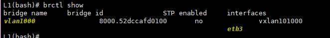
From the data plane perspective -traffic from GreenHost1 hits the eth3 interface on Leaf-1, where it’s bridged using the Vlan1000 bridge to the vxlan101000 interface^
And here’s what we can find out about this vxlan101000:
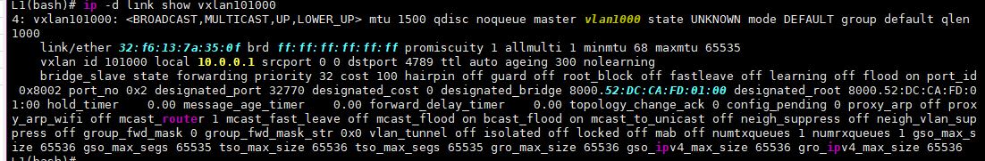
There’s a lot here, but the interesting bits for us are:
VXLAN ID: 101000
Local 10.0.0.1: The local IP address used for VXLAN encapsulation.
nolearning: This usually indicates that we’ve ditched the Flood&Learn approach in favor of a control plane—in our case, obviously, EVPN.
Some info on the MAC table’s state:
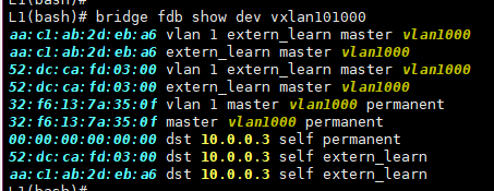
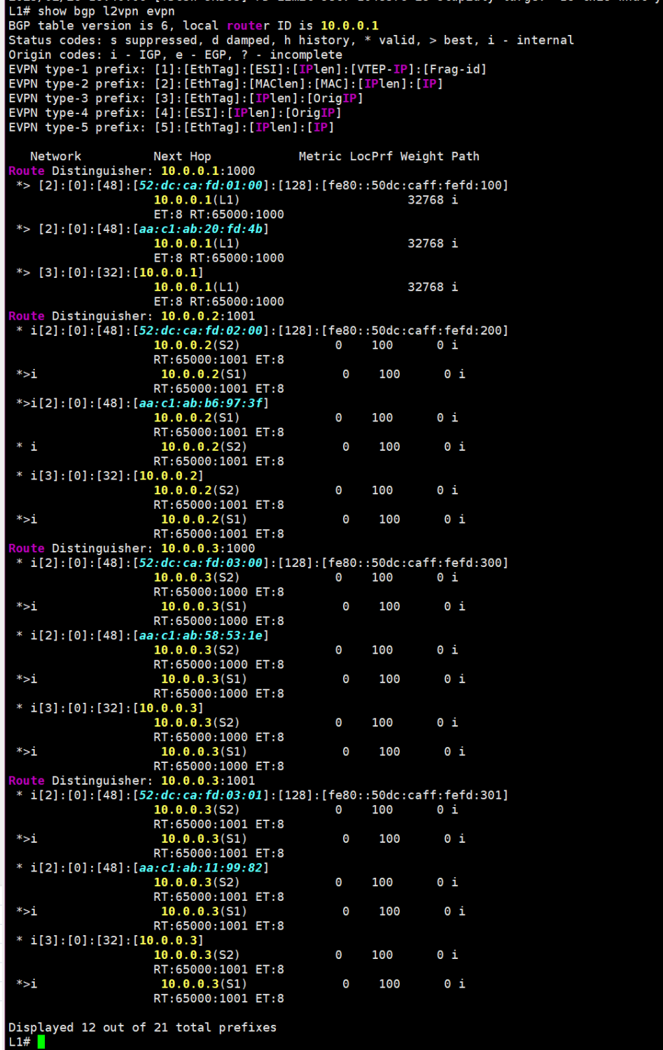
You can see that a couple of MACs came from the remote VTEP — 10.0.0.3 (that’s our Leaf-3). These MACs arrived as EVPN Route Type 2 routes. Here they are (I turned off the EVPN session to the second spine to reduce the output):
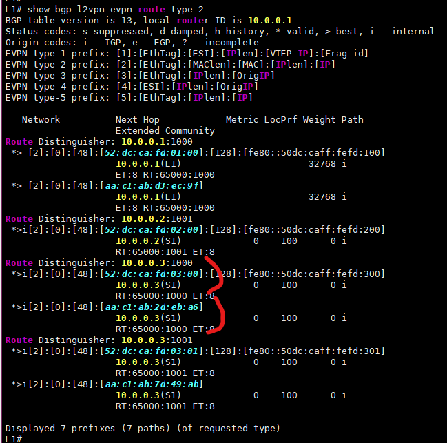
route type 2
The “ALL_ZEROS” MAC in the output above shows where we can send BUM traffic (Broadcast, Unknown Unicast, Multicast). This is typically generated by EVPN Route Type 3, which basically tells our router where to send BUM traffic for a specific VNI, just in case:
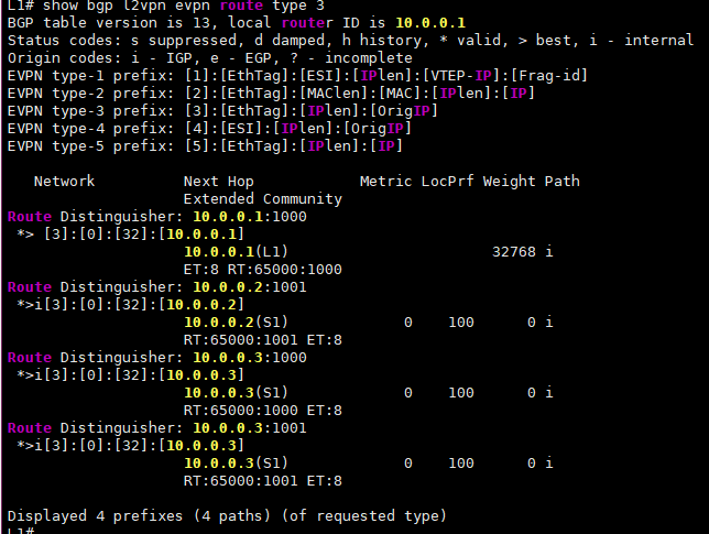
route type 3
And for all this to work at the kernel level, we need to enable support for VXLAN and encapsulation:
modprobe vxlan
modprobe ip6_udp_tunnel
modprobe udp_tunnel
So, that’s how EVPN with VXLAN works on FRR! 😎
Conclusions:
FRR is awesome.